


Finished polymer melt filter elements in factory
In today's complex and ever-changing industrial environment, metal filter elements have become an indispensable component for a variety of liquid and gas filtration. Understanding and proficient use of key filter terms is critical to ensuring effective system operation. This article will delve into a series of key terms, covering core concepts related to filter performance, cleanliness, durability, and more.
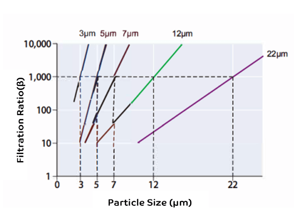
The filtration ratio or β value refers to the particle removal capacity value of the filter specified in ISO 16889 (multiple pass performance test of filter element), which is derived from the following formula:

After multiple pass tests, the average filtration ratio β is expressed in terms of particle size corresponding to 1,000. Refer to the table below:
Finished polymer melt filter elements in factory
The definition of cleanliness level comes from the number of solid particles in each milliliter of fluid, which is usually measured using an automatic particle counter. There are two commonly used evaluation methods: ISO 4406 and NAS 1638.
ISO 4406 expresses the contamination level in a three-digit format, with each digit representing the quantity of particles of 4 μm, 6 μm, and 14 μm respectively. The larger the number, the higher the quantity of contaminant particles.
NAS 1638 uses a concise code to express the cleanliness level, with the worst level of contamination in each grade being used as the cleanliness level. The smaller the number, the lower the quantity of contaminant particles.
The ability of a filter element to capture and retain solid particle contaminants from the beginning of use until the pressure drop reaches the specified end point, usually expressed in grams (g). This indicator is determined through multiple-pass tests (Filtration Performance Test or Multi-Pass Test) according to ISO 16889.
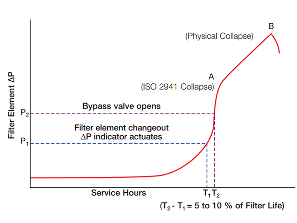
According to ISO 2941, it refers to the maximum difference in upstream and downstream pressure that the filter element can withstand without structural damage when clogged by contaminants.
The differential pressure of the filter rises as the filter media traps more contaminants. Before the bypass valve opens, a differential pressure indicator signals that the filter element should be replaced. The bypass valve protects the filter and system from excessive differential pressure and subsequent cartridge collapse.
Finished polymer melt filter elements in factory
The difference in pressure upstream and downstream of the fluid is the differential pressure of the filter assembly. Fluid through a clean new filter element, the difference between the upstream pressure of the filter element and the downstream pressure difference is called the initial differential pressure of the filter element. With the accumulation of pollutants in the use of the cartridge, the media flow through the cartridge resistance will gradually increase, the differential pressure will rise, the greater the viscosity of the fluid, the greater the resistance to circulation, the higher the value of the differential pressure. The medium flows through the filter housing without the filter element, it is called the filter housing differential pressure.
Used to describe the flow characteristics of the medium, the higher the viscosity of the medium, the greater the resistance to flow. Commonly used expression kinematic viscosity, the unit is mm2/s, and the symbol is cSt. Usually, the higher the temperature of the medium, the lower the viscosity. For example, hydraulic fluid No. 46, with viscosity code VG46, refers to a kinematic viscosity of 46 cSt at an oil temperature of 40 °C.
The filter can work continuously without structural damage, the system is applied inside the filter, and the pressure value is stable at the highest pressure index.
Filter in the system, can withstand a certain amount of alternating pulse pressure, rated fatigue pressure index from the simulation test to verify. Usually, the rated fatigue pressure of filter products is lower than the maximum working pressure.
The maximum pressure that the filter housing can withstand without structural damage.
1.5 times of the maximum use pressure of the filter, tested by a special test bench in a safe box. Before the filter leaves the factory, it is sampled and inspected according to the specification. For cast-iron type high-pressure filter parts, 100% of them shall be tested for pressure resistance.
Filter, cartridge maximum flow rate: filter or cartridge, in the maximum acceptable pressure drop conditions, can pass the maximum flow rate.
Filter cartridge life in actual use is the total length of time from the beginning of use to the differential pressure alarm device alarm.